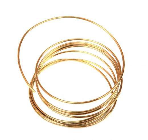
Wedge bonding is a automated process to attach connection leads between electronic components and a printed circuit board (PCB). The process entails bonding a wire connector to a terminal on the component and a PCB with a combination of pressure and either ultrasonic (U/S) or thermosonic (T/S) energy. The device used to feed the connector wire and transfer the pressure and energy to the bonds is a flat, wedge-shaped component that gives the bonds their characteristic shape and the process its name. Wedge bonding typically uses aluminum or gold alloy wires and can bond the aluminum wire at room temperature with U/S energy or gold alloy wire with T/S energy. When compared to other processes such as ball bonding, wedge bonding has the disadvantages of lower production speeds and restrictions in the range of angular flexibility between component and PCB bonds.
One of the most important stages of PCB construction is tying up the plethora of component terminals with their corresponding circuit points on the PCB substrate. Connections have to be well made to ensure circuit integrity; the physical connector wires also have to be placed in such a way as to occupy the minimum of space. All of this is typically carried out on an almost microscopic scale by highly sophisticated and accurate automated machines. Wedge bonding is one of the two most common processes for making these connections; the other is ball bonding.

The bonding head in wedge bonding machines is a flat plate equipped with a feed hole in its lower rear surface and a wedge shaped pressure shoe on the lower front edge. The connecting wire feeds through the hole at the back of the plate and is compressed and bonded with the wedge. The bond is created by a combination of pressure applied by the wedge shoe and either ultrasonic or thermosonic energy. U/S energy is a localized concentration of high frequency acoustic vibrations which causes a permanent bond and is used primarily for aluminum connecting wires. T/S energy is a combination of ultrasonic and conventional heat energy that bonds gold alloy wires.
The wedge bonding process is a multistep process which begins with the wedge descending on the component terminal. Once in contact with the terminal pressure, either U/S or T/S energy is applied to bond the wire. The wedge then raises up to a predetermined height and moves back to the position of the PCB terminal. This simultaneous raising and retreating movement pulls enough wire through the wedge to form a suitable loop or arch of wire between the component and the PCB. The wedge then descends and bonds the connector to the PCB.
Once the PCB bond is completed, the wedge raises and simultaneously cuts the wire before advancing to the next set of terminals. Wedge bonding is a little slower than the alternative ball bonding process and can generally only bond connectors which travel in a straight line between component and PCB terminals. It does, however, produce a smaller bond “footprint” and is thus suitable for bonding closely spaced terminals.
