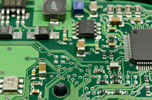
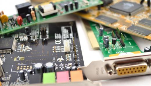
A printed circuit board is a component of most electrical appliances and electronic devices that basically serves as a conductor, helping currents get where they need to go and do what they need to do. These boards essentially act as maps to a device’s circuitry system. They have a number of grooves and holes through which currents can flow and other circuitry elements can be attached. A lot of precision is involved in their creation, and engineers usually spend a lot of time ensuring that they’ve been properly etched and treated. Once a board is assembled, it powers and in many respects gives life to the device in question. Problems with this board often mean that the device loses operability.
Basic Concept

Most electronics depend on internal circuitry in order to delegate things like electrical follow and power issues to various components. The actual science and engineering behind circuit boards can be somewhat complicated, but in simple terms the circuit board is a sort of “headquarters” or “terminal” where everything is processed and sorted. When viewed in isolation, the boards often look like thin metal plates marked with shiny grooves and etchings. Their size varies based on the device at issue, but can be as small as a fingernail or as large as a small car depending on context.
Assembly

Printed circuit boards serve as a foundation and mechanical support for electronic components. In general they are non-conductive surfaces, but they are populated with conductive pathways, signal traces, and electronic components as they are assembled in order to enable the flow of electrical currents. Once put together, the board is usually referred to either as a printed circuit board assembly (PCBA) or a printed circuit assembly (PCA).

Printed circuit board assembly is one of several methods of creating circuits, along with wire-wrapped circuits and point-to-point circuits. Assemblies tend to require greater effort for layout and a higher initial cost than the other available options, but they are more cost-effective over time and frequently also offer greater reliability. After taking initial costs associated with the circuit board design into account, board manufacturing is often less expensive and also offers quicker high-volume production than other methods.
Core Components
The materials used in manufacturing PCAs can vary depending on how they will be used. Typically, the conducting layers are made of a thin copper foil, and the dielectric insulating layers are laminated together using epoxy resin. Often, what is known as a “blank board” is created when the substrate is completely covered on one or both sides by a copper bonding layer. A temporary mask is applied next, allowing any unwanted copper to be removed by way of pattern etching.
Etching Methods
In most cases, the board’s signature grooves and indentations have to be specifically pressed, or etched, into the surface. Photographic printing and silk-screen printing are the most common methods of etching for commercial purposes. Photoengraving relies on a photomask and a chemical process to remove unwanted copper. Etching processes typically use ammonium persulfate, ferric chloride or hydrochloric acid to eat away unwanted layers of copper. Silk-screen printing relies on inks that are etch resistant, protecting the underlying copper foil so that only the unwanted copper is etched away. Another option is milling, which requires a special machine to remove the copper.
In some construction methods, traces are added to rather than removed from the substrate. This typically is done through electroplating. The chosen manufacturing method for a printed circuit board will vary depending on whether the board is a one-off or must be reproduced in large quantities.
Choosing an Insulator
One of the most important parts of board assembly involves insulation to protect the board from overheating or becoming clogged with signals. There are different types of dielectric material available for this purpose, including composite epoxy material (CEM) and flame-retardant (FR) material, and each provides a different insulating value depending on the circuitry requirements. Teflon, FR-1, FR-4, CEM-1 and CEM-3 are some examples of dielectrics. Materials commonly used in PCB construction include phenolic cotton paper (FR-2), cotton paper with epoxy (FR-3 and CEM-1), woven glass with epoxy (FR-4), and matte glass with polyester (FR-6).
