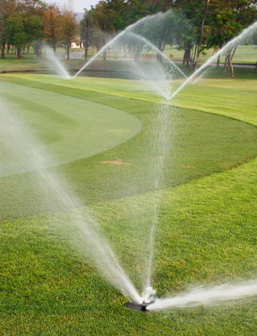
An irrigation controller is the brain or control center of any dedicated garden irrigation system. This device is typically installed as a first point in an irrigation layout and determines which parts of the system will activate and when. This control may be achieved via preprogrammed information stored in the irrigation controller or from the inputs of moisture sensors in the garden itself. Controllers may be simple devices which feature a single water line with a couple of sprinkler points or extremely complex systems featuring miles of water lines and hundreds of outlets. Depending on the type of installation, the irrigation controller may be a small, unobtrusive enclosure connected to a garden tap or a sophisticated, computer based setup such as those used to irrigate golf courses and estates.
Most garden buffs find walking around the garden in the evening while watering flower beds to be a relaxing and enjoyable experience. The picture is a little different for busy homeowners who lack the time to tend their gardens every day or landscape managers with extensive areas to care for. The irrigation controller can make light work of keeping up with the watering requirements of the biggest, or smallest, gardens with very little operator input. These controllers generally consist of a distribution manifold which sends water to specific points via a series of valves. A controller unit dictates which valves will activate and when to irrigate different areas or zones in the garden.

Although most irrigation controllers operate on a common basic principle, the user interfaces differ considerably between models. Smaller controllers consist of a single cabinet which will typically have a set of controls and a liquid crystal display (LCD). The controls allow the user to preprogram the areas of the garden to be watered, on which days, and for how long. The simplest of these may feature a single zone output although most allow for at least three or four different areas in the garden to be controlled. The actual irrigation hoses run through solenoid valves out to theses zones where they are terminated with drip points, sprays heads, or mechanical pop-up sprinklers.
The solenoid valves are typically located close to the irrigation controller cabinet to preclude the need for lengthy cable runs. The valve switching outputs are then run from the controller to the valves. When the controller program or timer reads a zone watering flag, it will send the appropriate valve an electrical signal, and the area will be irrigated until the controller turns the valve off again. The flags or active watering time signals may be a simple tab on a mechanical timer, part of a onboard program, or even an external input. These external inputs are often supplied by moisture sensors placed in the different irrigation zones.
Larger systems such as those used on estates and golf courses are far more complex and often run from a computer in a central control facility. The basic principle remains the same, although user inputs or outside sensor readings control a series of valves to irrigate certain zones at specific times. The main difference between these and the smaller systems is the amount of peripheral functionality. These functions may include diagnostic reporting, graphic representations of zone status, increased flexibility regarding zone control, and even online weather service integration.
